

Technology

Vertical Combustor
Refined & Proven Incineration Technology
Stable Combustion with Simplified Design
Waste is fed into a tall, vertical furnace and falls into the primary chamber at the bottom. There it is broken down by heat, and the resulting gas rises to the upper chamber to be burned. This simple design keeps the process stable, efficient and easy to maintain.
How it works
Loading. Waste is fed in by conveyor or crane. A double-damper loading device keeps the furnace sealed while waste enters.
Pyrolysis. Waste falls into the primary chamber at the bottom of the furnace, where only a small amount of air is supplied. With little oxygen, the waste does not burn completely. Instead, it breaks down into combustible gas and carbon-rich material (char) through pyrolysis and carbonization.
Clean burning. The combustible gas rises to the upper secondary combustion chamber, where extra air is added and the gas burns completely. This reduces harmful emissions.
Complete burnout. The char stays in the primary chamber long enough to burn down to ash.
Ash removal. The ash drops into a water-sealed conveyor under the furnace and is carried out.
Why it matters
Two-stage combustion. The furnace burns the solid waste first, then burns the gas it produces. This gives a thorough burn and keeps harmful substances low in the flue gas, even before it enters the flue gas treatment system. Very little unburned material is left in the ash.
High combustion efficiency. Once running, the furnace needs no auxiliary fuel during normal operation. This helps keep running costs down.
No moving parts in the high-temperature zone. Parts that move are not exposed to the hottest areas of the furnace. This means less wear and high durability.
Applicable for various types of waste

Sludge
~1,000 kcal/kg
(4.2 MJ/kg)

Municipal solid waste
~3,000 kcal/kg
(12.6 MJ/kg)

Industrial waste
~4,000 kcal/kg
(16.7 MJ/kg)

Infectious medical waste
~6,000 kcal/kg +
(25.1 MJ/kg +)
Flow diagram
Waste-to-Energy Plant

Incineration Plant
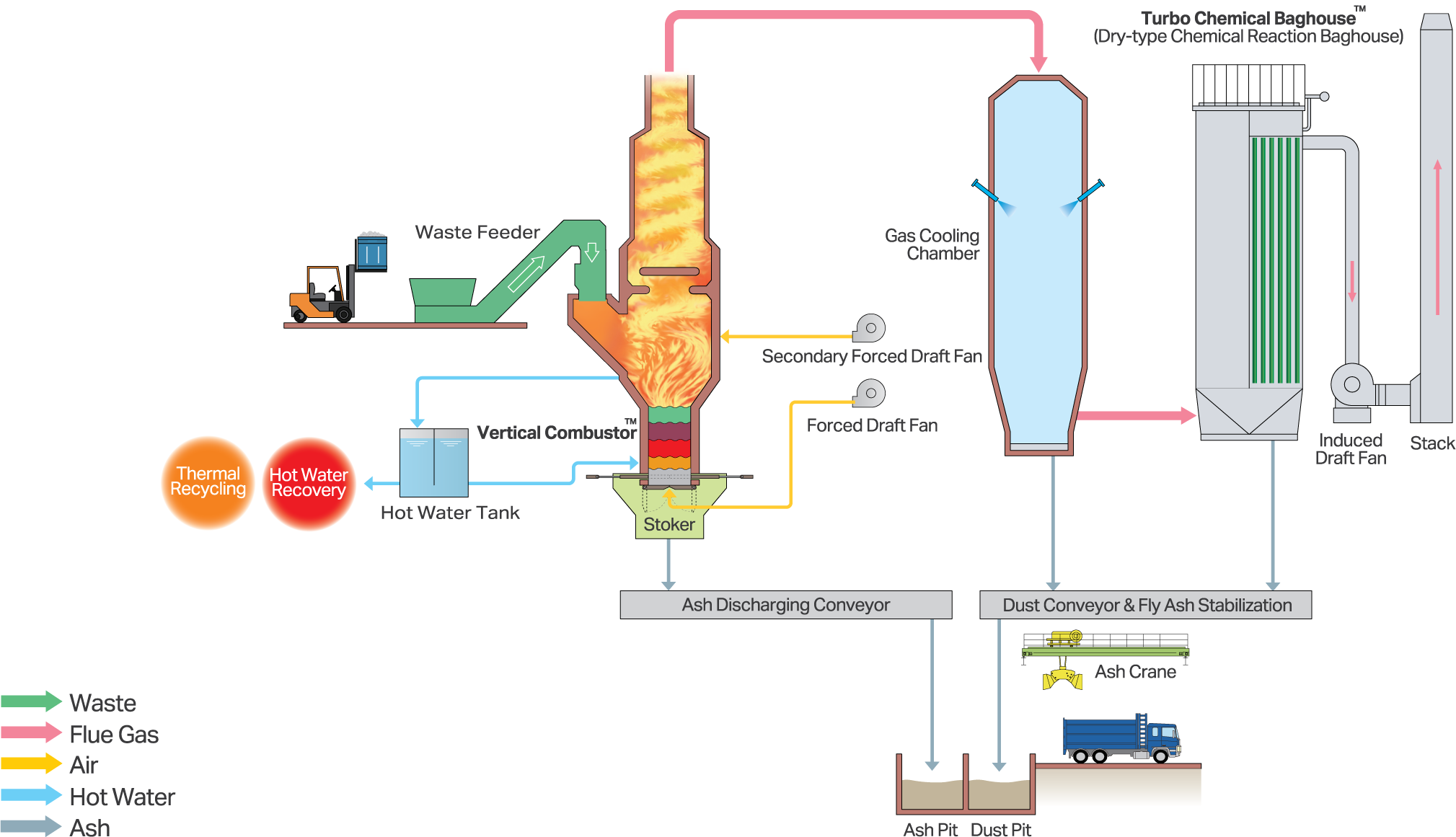
Key features
-
Small, fixed amount of primary combustion air blown from furnace bottom uniformly passes through waste layer.
-
Fresh waste dropped on top of the waste layer with relatively high moisture content is not burned immediately, but is completely dried by the hot pyrolysis gas rising from the pyrolysis zone.
-
Since the primary combustion air ratio is low, a larger amount of secondary combustion air can be injected into the secondary combustion chamber to ensure efficient combustion of the flue gas to minimize the generation of pollutants.
-
Vertical Combustor incinerators can be operated automatically or manually using PLC/DCS.
-
The plant equipped with a vertical combustor can operate continuously for 24 hours or intermittently. It can be started up in just 30 minutes, resulting in lower fuel consumption. Additionally, there are no issues with flue gas treatment, even during the period from shutdown to the next start-up.
-
Thermal recycling can be achieved through power generation, steam/hot water production, or the utilization of absorption chillers. Since combustion remains stable, power generation from waste incineration becomes highly efficient, ensuring a consistent generation of steam.

Commercial advantages
-
The fed waste is combusted by the heat content of the waste itself, so no auxiliary fuel is required during normal operation. Auxiliary fuel such as heavy oil is used only during start up and shutdown of the plant.
-
All wastes of different characteristics and quality are converted into fuel (carbide and combustible gases) by pyrolysis process and then incinerated. Therefore, waste separation is not required.
-
Due to its simple structure and fewer moving parts, it is relatively easy to operate. A minimum of 3 people are required to operate the system.
-
Fewer mechanical problems because there are no moving parts in the high temperature zone, and the number of moving parts themselves is much less than the other types of incinerators such as moving stoker and rotary kiln incinerators.
-
Due to its vertical structure, the land area required is less than other types of incinerators.

Turbo Chemical Baghouse
Dry Type Chemical Reaction Dust Collector


Efficient Flue Gas Treatment
Turbo Chemical Baghouse
Conventional Baghouse
Technical features & advantages
-
The thick precoat layer of chemicals (slaked lime and/or activated carbon) increases the contact efficiency between the chemicals and hazardous gases, so that the removal efficiency is equivalent to that of wet treatment such as water scrubber, even though it is a dry treatment. In addition, wastewater treatment is not required as in the wet process.
-
The thick precoat layer of chemicals formed on the filter cloth can reduce damage to the filter cloth caused by acid gas, thus extending the service life of the filter cloth.
-
High efficiency of contact between flue gas and chemicals reduces unreacted chemicals and chemical consumption. The reduction in the amount of chemicals used also reduces the amount of fly ash, which reduces not only the cost of chemicals, but also the cost of final disposal of fly ash.
-
The precoat layer ensures that dioxins, high concentrations of hydrogen chloride, sulfur oxides, mercury and other heavy metals, and other difficult-to-remove toxic substances can be reacted and adsorbed for removal. The flue gas emission standards of not only Japan, Singapore, and Indonesia, but also EU can be met by dry treatment only.

Watch video
Contact us
We’re always looking for new opportunities and are comfortable working internationally.
Please get in touch and one of our project managers will contact you about beginning the proposal process.
Plantec Asia Pacific Pte Ltd
Phone: +65 6222 1114
Email: info@plantec-ap.com